38 electric motor diagram with labels
EEP - Electrical Engineering Portal | Energy and Power For All Electric Motor ♛ Main and auxiliary circuit diagrams of switching pole-changing three-phase motors. This technical article is dedicated to the main and auxiliary circuit diagrams of switching three-phase motors. We’ll now discuss a little more complicated schematics than the previous article. We’ll cover... Read more. May 23, 2022 | By edvard electric engine diagram with labels Wiring diagrams 911: honda cb125s motorcycle electrical circuit diagram. Patent us8548694 UNPh30. 16 Pics about UNPh30 : 1941 Harley Davidson WL Restoration : Another H-D WL Wiring Diagram, draw a neat labelled diagram of simple electric motor - Brainly.in and also Wiring Diagrams 911: Honda CB125S Motorcycle Electrical Circuit Diagram.
Electric Motor Nameplate Details Explained | Electric Motor ... The nameplate shown in Figure 1 indicates the electric motor is rated 1 HP. With a service factor of 1.15, the motor can be overloaded up to 1.15 horsepower. If the motor is operated in the service factor range continuously, it will cause a reduction in motor speed and efficiency, and an increase in the motor's operating temperature.

Electric motor diagram with labels
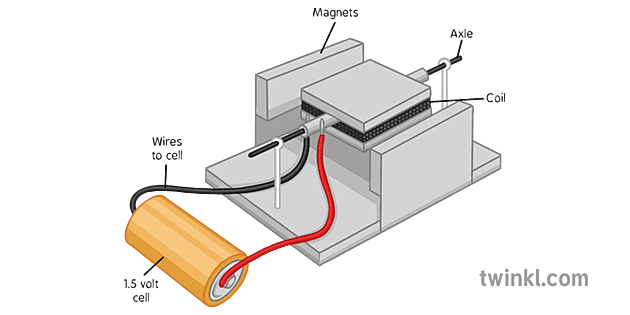
Electric Motor - Parts of Motor, Working of Electric Motor & Uses - Byju's Take two bar magnets and keep the poles facing each other with a small space in between. Now, take a small length of a conducting wire and make a loop. Keep this loop in between the space between the magnets such that it is still within the sphere of influence of the magnets. Now for the last bit. Connect the ends of the loop to battery terminals. Electric Motor Starting Capacitor Selection - Select an A/C ... Supco, Sealed Unit Parts Company, PO Box 21, 2230 Landmark Place, Allenwood, New Jersey, 08720, Tel: 732-223-6644, 201-449-3300, email: info@supco.com, provided the compressor starting capacitor and packaging information (purchased by the author from an air conditioning parts supplier in New York) - our example uses a Sealed Unit Parts Company Solid State part No. RSC 10 115V starting ... Electrical Diagrams and Schematics - Inst Tools Types of Electrical Diagrams or Schematics There are three ways to show electrical circuits. They are wiring, schematic, and pictorial diagrams. The two most commonly used are the wiring diagram and the schematic diagram. The uses of these two types of diagrams are compared in Table 1.
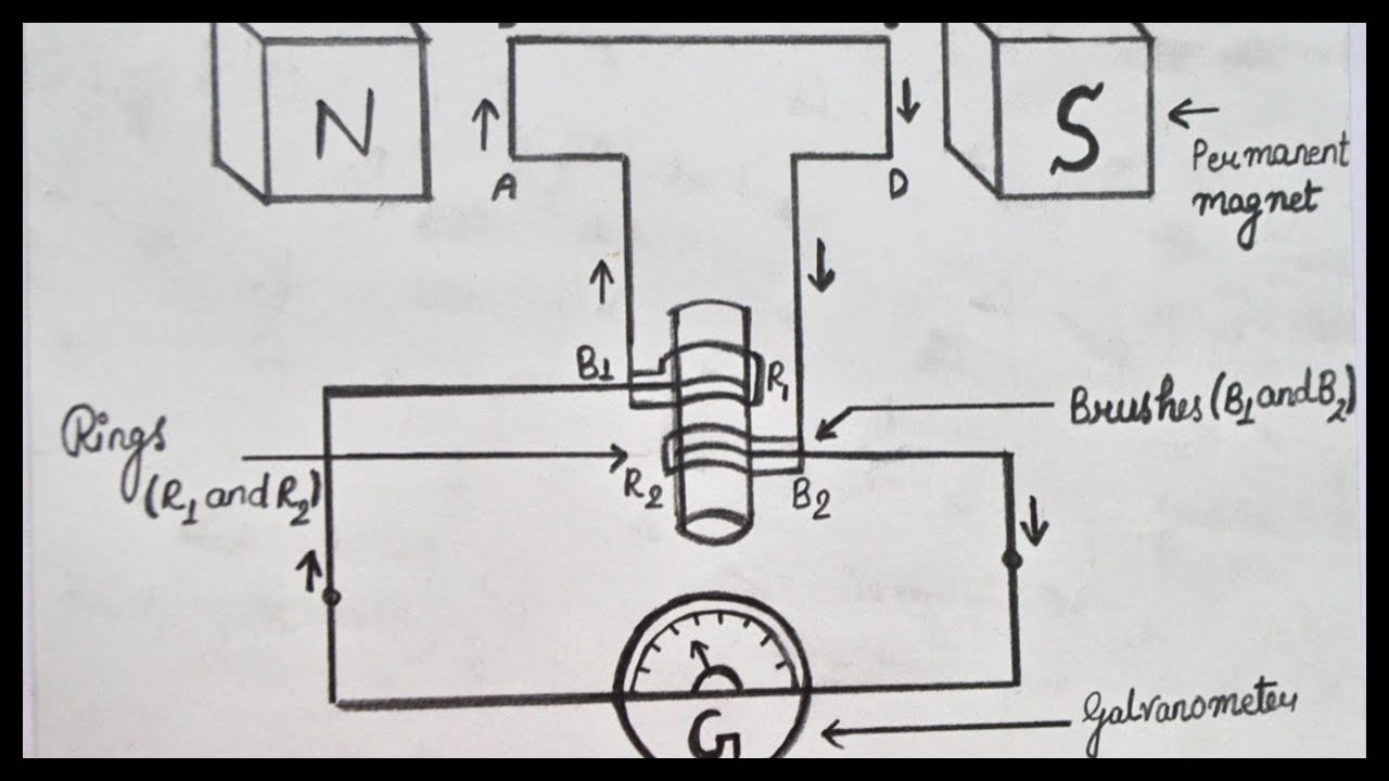
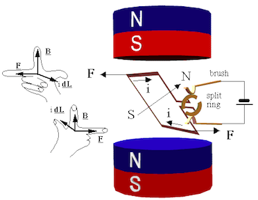
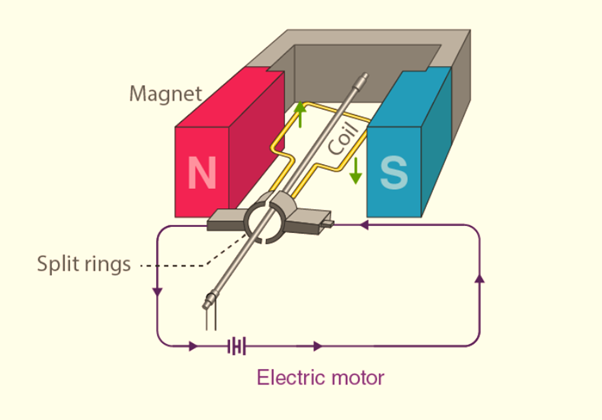
Electric motor diagram with labels. Connection Diagrams - Nidec Connection Diagrams. 6 Lead, Wye or Delta Connection, Single Voltage Full Winding - Across the Line Start. 6 Leads Out, Wye Connection, Single Voltage, Full Winding - Across the Line Start. 6 Lead, 1.73 to 1 Ratio Dual Voltage or WYE Start - DELTA Run on Low Volts. 2 Speed, 2 Winding, Single Voltage, Wye Connected, With Current Transformers ... PDF Electrical Symbols and Line Diagrams - University of Florida Electrical Symbols and Line Diagrams - University of Florida Motor Connection Diagrams - Electric Motor Warehouse Single Phase Terminal Markings Identified By Color: (NEMA Standards) 1-Blue 5-Black P1-No color assigned. 2-White 6-No color assigned P2-Brown. 3-Orange 7-No color assigned. 4-Yellow 8-Red. Three Phase Connections: Part Winding Start: 6 Leads NEMA Nomenclature: WYE or Delta Connected. NCERT Q11 - Draw a labelled diagram of an electric motor. Explain - teachoo Draw a labelled diagram of an electric motor. Explain its principle and working. What is the function of a split ring in an electric motor?AnswerElectric Motor looks likePrinciple of an electric motorAn electric motor works on the principle thatwhen a rectangular coil is placed in a magnetic field a
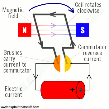
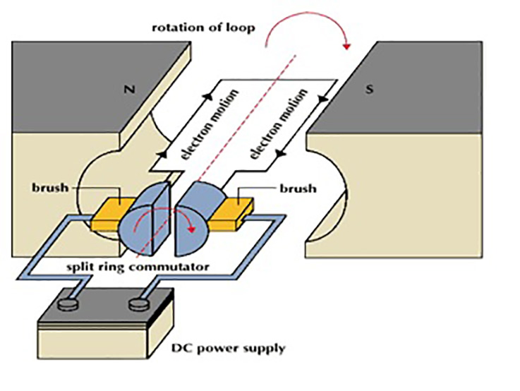
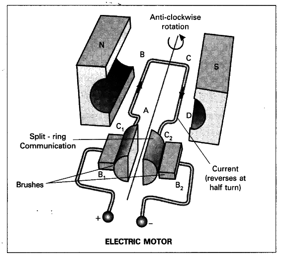
General Electric Motor Wiring Diagram - Database The white wire is the neutral wire and switches into the neutral airport terminal, which is marked by silver/light-colored anchoring screws. The black line, on the other hand, is the hot wire and goes into the hot terminal, the one opposite the neutral terminal. The picture shows a basic diagram of an electric motor. At top left a ... The picture shows a basic diagram of an electric motor. At top left a piece of magnet labeled N and at top right a piece labeled S. Between these a square coil of wire X sits attached to a metal rod, which runs between the 2 pieces of magnet. 2 semicircular pieces Z of metal surround the rod at its opposite end from the pieces of magnet. YouTube About Press Copyright Contact us Creators Advertise Developers Terms Privacy Policy & Safety How YouTube works Test new features What is an Electric Motor? with the Help of a Labelled Diagram ... An electric motor is a device that converts electrical energy into mechanical energy. Diagram: Electric motor Working of an electric motor: An electric motor works on the principle of magnetic effect of electric current.
Join LiveJournal Password requirements: 6 to 30 characters long; ASCII characters only (characters found on a standard US keyboard); must contain at least 4 different symbols; Three Phase Motor Power & Control Wiring Diagrams - ELECTRICAL TECHNOLOGY Three Phase Motor Connection STAR/DELTA Without Timer - Power & Control Diagrams. Three Phase Motor Connection Star/Delta (Y-Δ) Reverse / Forward with - Timer Power & Control Diagram. Starting & Stopping of 3-Phase Motor from more than One Place Power & Control diagrams. Control 3-Phase Motor from more than Two buttons - Power & Control ... How To Read An Electric Motor Nameplate Usually labeled as HP or kW, this is the measure of the motors ability to deliver the torque required for the load at a rated speed. hp = 0.746 x kW; conversely, kW =1.34 x hp. Time Rating or duty (DUTY). This designation specifies the length of time that the motor can safely carry its nameplate rating. Motor Connection Diagrams (OLD LECTURE) - YouTube Please use the updated lecture at:
Electrical Motors Basic Components ~ Electrical Knowhow ...
Electric Motor Wiring Diagram 220 to 110 Sample A wiring diagram is a straightforward visual representation in the physical connections and physical layout of the electrical system or circuit. It shows how a electrical wires are interconnected and may also show where fixtures and components might be attached to the system. When and How to Use a Wiring Diagram

Science online exercise for GRADE 10
AC Motor Control Circuits Worksheet - AC Electric Circuits After the motor has had time to speed up, another set of “starter” contacts bypass line power around the resistors, directly to the motor windings. Draw a diagram showing how this could be done for a single-phase electric motor, using two starter contacts: “R” for “run” and “S” for “start”.
Electric motor - Energy Education
Electric Motors Symbols - AC/DC, Single Phase / Three Phase Motors This is the symbol of a generic electrical motor that is used in electrical schematics. A motor converts electrical energy into mechanical energy. Dual Speed Motor This symbol represents a dual speed motor. Such type of motors has two separate windings for different speed ratios. Each winding provide different speed & torque at a single time.
Draw a labelled diagram of an electric motor Expla - Tutorix
Electric Car Diagram | Car Construction Suspension elastic elements. Car Wheel Anatomy. ELECTRIC CAR. Batteries for Electric cars. Hybrid Construction. Battery lifetime. Electric Motors construction. Permanent magnet synchronous motor. Replacing electric car batteries.

Draw a labeled diagram of an electric motor. Explain its ...
The Asahi Shimbun | Breaking News, Japan News and Analysis Oct 15, 2022 · The Asahi Shimbun is widely regarded for its journalism as the most respected daily newspaper in Japan. The English version offers selected articles from the vernacular Asahi Shimbun, as well as ...
Draw the diagram of a simple electric motor. Label the ...
How to read single one line diagram | Electric Arc - ArcAdvisor Motor Represents a motor and is also shown with an “M” inside the circle. Additional motor information is commonly printed next to symbol, such as horsepower, RPMand voltage. Normally open (NO) contact Can represent a single contact or single pole switch in the open position for motor control Normally closed (NC) contact

Magnetic Effect of Electric Current NCERT Exemplar Problems ...
Electric Motor Symbols - Electrical Symbols Electric motors are electromechanical devices whose function is to transform electrical energy into mechanical energy through electromagnetic interactions. There are other engines ( generators) that produce electricity by exploiting the mechanical energy, such as alternators and dynamos. It may interest you...
DC Electric Motors
Draw a labelled diagram of a d.c. motor. - toppr.com Draw a labelled diagram of a d.c. motor. Medium Solution Verified by Toppr Principle of a simple electric motor is when a rectangular coil carrying current is placed in a magnetic field, a torque acts on the coil which rotates it continuously. When the coil rotates, the shaft attached to it also rotates and thus it is able to do mechanical work.

Draw a labelled diagram of a d.c motor showing its main parts ...
Electric Motor Diagrams - Mr. Electrician's Home Page A Repulsion Electric Motor is by definition a single phase motor which has a stator winding arranged for connection to the source of power and a rotor winding connected to a commutator. Brushes and commutators are short-circuited and are placed so that the magnetic axis of the rotor winding is inclined to the magnetic axis of the stator winding.

Draw the diagram of a DC motor and label the parts.
Single Phase Electric Motor Wiring Tutorial: Baldor, WEG, Leeson In this video, Jamie shows you how to read a wiring diagram and the basics of hooking up an electric air compressor motor. These tips can be used on most ele...
What is an Electric Motor? with the Help of a Labelled ...
How to Read an Industrial Pump Motor Wiring Diagram Each motor has several wires in it which are labeled with letters and numbers. For "Line", take the wires the diagram instructs, wrap them together, and connect them to the incoming voltage. For "INSUL", take the wires, wrap them together, and twist them into an insulated cap. Once this is done, the motor is ready to be turned on.
How to Draw Electric Generator Step By Step For Beginners || Electric Motor Drawing || Pencil Art
DC Series Motor Working and Its Applications - ElProCus DC Series Motor Circuit Diagram. In a series motor electric power is supplied between one end of the series field windings and one end of the armature. When voltage is applied, current flows from power supply terminals through the series winding and armature winding. The large conductors present in the armature and field windings provide the ...
Electric Motor | Solutions
PDF Nuclear Regulatory Commission Nuclear Regulatory Commission

electric motor diagram - Google Search | Electric motor for ...
AC Motor - Basic Properties, Terminology and Theory - Galco Motors convert electrical energy into mechanical energy, and the resulting motion and torque drives a load. The most effective motor control solution is the variable frequency drive, or adjustable speed drive. Drives vary motor input frequency and voltage to control motor speed and torque. Networking & Communication. Ethernet Switches.

label diagram of electric motor - Brainly.in
Electric Motor - Principle, Working, Diagram - Explained step by step (a) An electric motor converts mechanical energy into electrical energy. View Answer NCERT Question 11 - Draw a labelled diagram of an electric motor. Explain its principle and working. What is the function of a split ring in an electric motor? View Answer NCERT Question 12 - Name some devices in which electric motors are used. View Answer

Draw a labeled diagram of an electric motor. Explain its ...
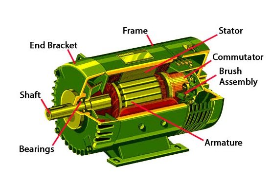
7 Parts Of Simple Electric Motor And Function - AutoExpose The trunk, the magnet is placed on a pivot with the circuit in such a way that it can produce rotary motion when these two components interact. Electric Motor main Components 1. Stator Coil 2. Rotor Coil 3. Main Shaft 4. Brush 5. Bearing 6. Drive Pulley 7. Motor Housing Simple Motor Parts and their function 1. Stator / Armature Coil

DC Motor Electrical Design Notes – PAKTECHPOINT
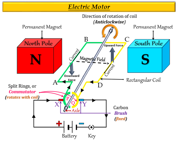
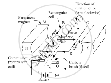
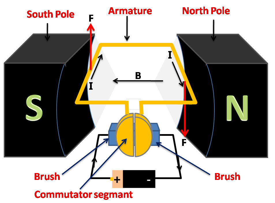
Question 11 Draw a labelled diagram of an electric motor. Explain its ... Principle: It works on the principle of the magnetic effect of current. A current-carrying coil rotates in a magnetic field. Working: When a current is allowed to flow through the coil MNST by closing the switch, the coil starts rotating anti-clockwise. This happens because a downward force acts on length MN and at the same time, an upward force acts on length ST.
Draw a labelled diagram of an electric motor Explain class 12 ...
What is an Electric Motor? Diagram & Working - ElectricalWorkbook Figure 1: An electric motor converts electric energy into mechanical energy. Working of an Electric Motor We know that when a conductor carrying a current is placed in a magnetic field, it experiences a mechanical force. The action of electric motor is based on this principle.
Electric motors and generators
Electrical Diagrams and Schematics - Inst Tools Types of Electrical Diagrams or Schematics There are three ways to show electrical circuits. They are wiring, schematic, and pictorial diagrams. The two most commonly used are the wiring diagram and the schematic diagram. The uses of these two types of diagrams are compared in Table 1.

Draw a labelled diagram of an electric motor. Explain its ...
Electric Motor Starting Capacitor Selection - Select an A/C ... Supco, Sealed Unit Parts Company, PO Box 21, 2230 Landmark Place, Allenwood, New Jersey, 08720, Tel: 732-223-6644, 201-449-3300, email: info@supco.com, provided the compressor starting capacitor and packaging information (purchased by the author from an air conditioning parts supplier in New York) - our example uses a Sealed Unit Parts Company Solid State part No. RSC 10 115V starting ...
Electric Motor Diagram Stock Illustrations – 891 Electric ...
Electric Motor - Parts of Motor, Working of Electric Motor & Uses - Byju's Take two bar magnets and keep the poles facing each other with a small space in between. Now, take a small length of a conducting wire and make a loop. Keep this loop in between the space between the magnets such that it is still within the sphere of influence of the magnets. Now for the last bit. Connect the ends of the loop to battery terminals.
8,681 Simple Electric Motor Images, Stock Photos & Vectors ...

Label the diagram of electric motor.Name C & D and mention ...
Basics of AC, DC, and EC electric motors, Part 1— AC and DC
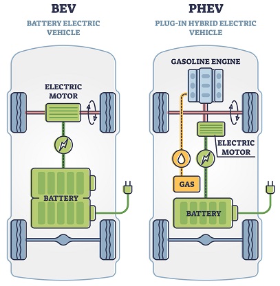
Types of electric vehicles with labeled battery and motor ...
Draw a neat diagram of electric motor. Name the parts - CBSE ...

Types of Electric Vehicles with Labeled Battery and Motor ...

Electric motor diagram hi-res stock photography and images ...
Electric Motor Science Diagram KS4 Illustration - Twinkl

Video lesson/Principles of Electric Motor and Generator
Analyze Electric Motor and Generator Designs (MPH-Files)
What is an electric motor? Explain its construction and ...
a) What is an electric motor? With the help of a labelled ...

How to draw diagram for Construction of an electric motor | How to draw electric motor diagram
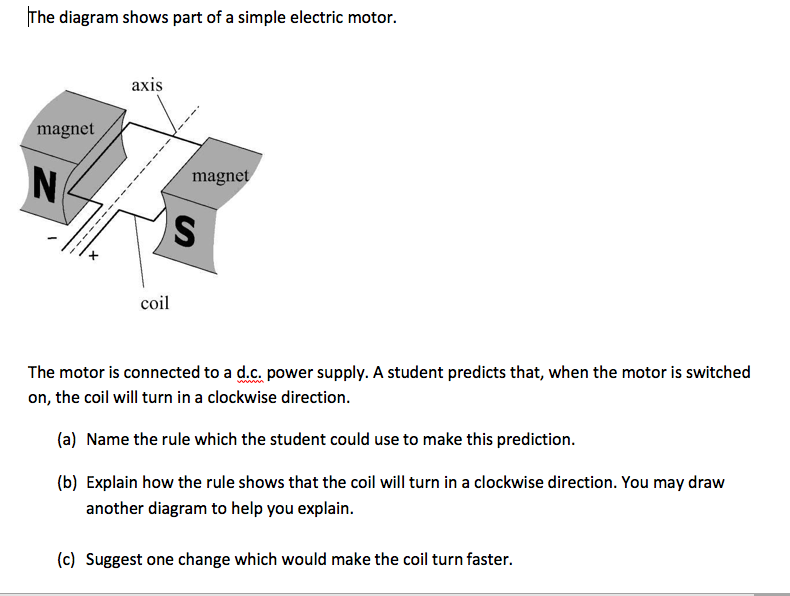
Solved The diagram shows part of a simple electric motor ...

Induction motor cutaway view with labels. | Download ...

DC Motor Diagram and Constructional Parts - ETechnoG
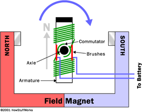
How Electric Motors Work | HowStuffWorks
Post a Comment for "38 electric motor diagram with labels"